Chapter 09 - Visual improvements and camera support
This is a transition chapter. We will add small improvements and present some new concepts to prepare more relevant changes in the next chapters (therefore, it will be a shorter chapter). We will improve the visuals by adding support for transparent objects and mipmaps. We will also add support for a camera to move inside the 3D scene.
You can find the complete source code for this chapter here.
Transparent objects
We need to add support to draw transparent objects so the pipeline must use the blending feature. The code for this is already present in the VkPipeline struct, but let's revisit and review carefully the parameters:
File: src/eng/vk/vkPipeline.zig
pub const VkPipeline = struct {
    ...
    pub fn create(allocator: std.mem.Allocator, vkCtx: *const vk.ctx.VkCtx, createInfo: *const VkPipelineCreateInfo) !VkPipeline {
       ...
        const pcbas = vulkan.PipelineColorBlendAttachmentState{
            .blend_enable = if (createInfo.useBlend) vulkan.Bool32.true else vulkan.Bool32.false,
            .color_blend_op = .add,
            .src_color_blend_factor = .src_alpha,
            .dst_color_blend_factor = .one_minus_src_alpha,
            .alpha_blend_op = .add,
            .src_alpha_blend_factor = .src_alpha,
            .dst_alpha_blend_factor = .zero,
            .color_write_mask = .{ .r_bit = true, .g_bit = true, .b_bit = true, .a_bit = true },
        };
       ...
    }
    ...
};
We need to setup the blending by filling up a PipelineColorBlendAttachmentState structure. We need to set up the following attributes:
blend_enable: We need to enable blending to support transparent objects. By setting this attribute totruethe colors are mixed when rendering.color_blend_op: Defines the blending operation for the RGB components. In this case, we are adding source and destination colors, so the resulting color components will be calculated according to this formula:R = Rs0 × Sr + Rd × Dr,G = Gs0 × Sg + Gd × DgandB = Bs0 × Sb + Bd × Db. As you can see, source and destination colors are added modulated by some factors (Sxfor source colors andDxfor destination colors). Source color is the new color to be mixed, and destination color is the one already present in the color attachment.alpha_blend_op: Defines the blending operation for the alpha components. In this case we are also adding source and destination colors:As0 × Sa + Ad × Da. As you can see, again, source and destination colors are added modulated by some factors (Safor source andDafor destination).src_color_blend_factor: This controls the blend factor to be used for the RGB source factors (Sr,SgandSb). In our case we are using thesrc_alpha(VK_BLEND_FACTOR_SRC_ALPHA) value, which sets those factors to the alpha value of the source color.dst_color_blend_factor: This controls the blend factor to be used for the RGB source factors (Dr,DgandDb). In our case we are using theone_minus_src_alpha(VK_BLEND_FACTOR_ONE_MINUS_SRC_ALPHA) value, which sets those factors to one minus the alpha value of the destination color.src_alpha_blend_factor: This controls the blend factor to be used for the alpha source component (Sa). In our case, we set it to the valuesrc_alpha(VK_BLEND_FACTOR_ONE), that is, it will have a one.dst_alpha_blend_factor: This controls the blend factor to be used for the alpha destination component (Da). In our case, we set it to the valuezero(VK_BLEND_FACTOR_ZERO), that is, it will have a zero, ignoring the alpha value of the destination color.
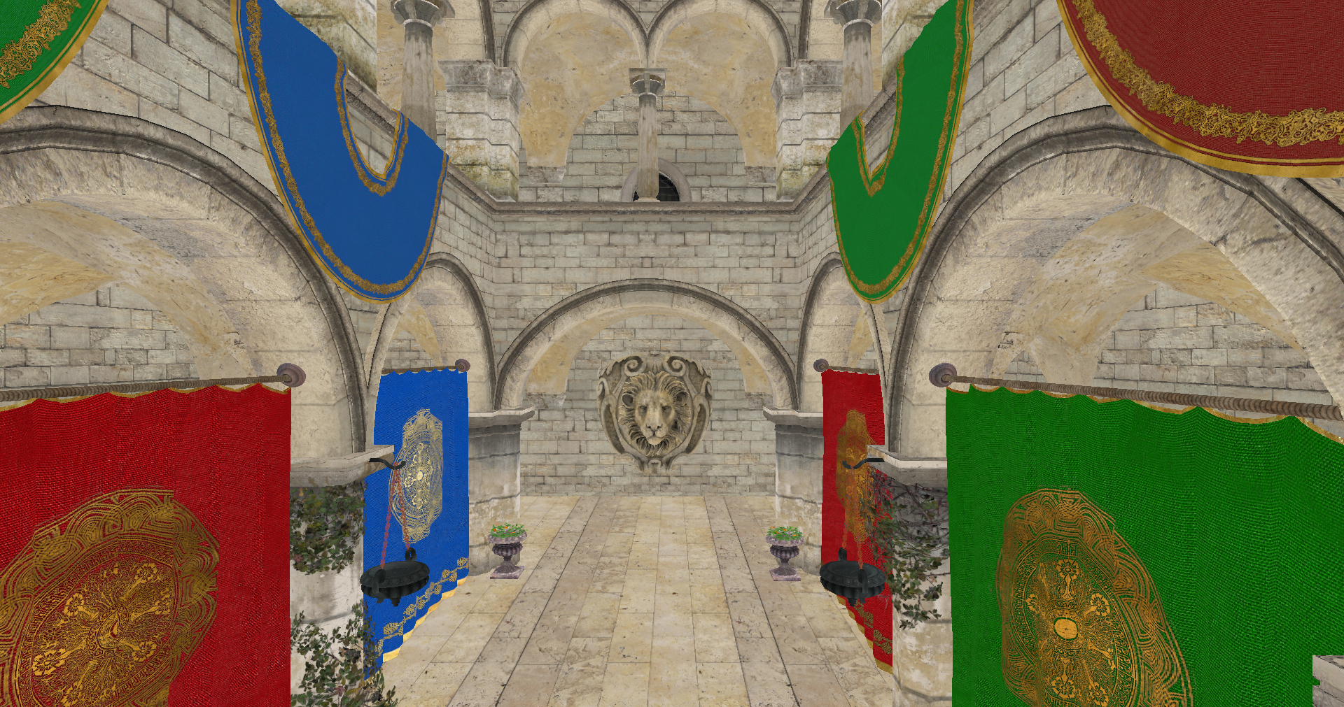
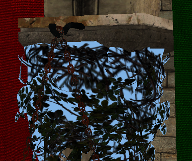
However, if you rendered a scene with just these changes, you may experience strange artifacts. Depending on the order that objects are rendering, you may have a transparent object, closer to the camera that gets rendered first than objects that are behind. This will make that the transparent object gets blended with the background, because the distant objects will be discarded in the depth test. The next figure shows this effect (It has been exaggerated with a non black background to see the effect).
In order to solve that, we are going to apply an easy fix, we will first draw non transparent objects to force transparent objects to blend with non transparent ones. This fix still can make some artifacts (if we have many transparent objects that overlap between them), but it is simple enough and produces good results. In order to apply that, we need first to have a way to check if an object is transparent or not. We will add this support in the VkTexture struct. We will add a new attribute named transparent that will hold true if the texture has transparent values. We will set up this attribute in the create function by calling a new function named isTransparent.
File: src/eng/vk/vkTexture.zig
pub const VkTexture = struct {
    ...
    transparent: bool,
    ...
    pub fn create(vkCtx: *const vk.ctx.VkCtx, vkTextureInfo: *const VkTextureInfo) !VkTexture {
        ...
        return .{
            ...
            .transparent = isTransparent(&vkTextureInfo.data),
        };
        ...
    }
    ...
    fn isTransparent(data: *const []const u8) bool {
        const numBlocks = data.len / 4;
        var transparent = false;
        for (0..numBlocks) |i| {
            if (data.*[i * 4 + 3] < 255) {
                transparent = true;
                break;
            }
        }
        return transparent;
    }
    ...
};
This new function basically, iterates over the image contents, checking if the alpha component has a value different than 255 (1.0 in normalized color components). If so, we consider that the texture has transparencies. With that information, we will add a new field to the VulkanMaterial struct which states if the material is transparent:
File: src/eng/modelsCache.zig
pub const VulkanMaterial = struct {
    ...
    transparent: bool,
    ...
};
We need also to update the MaterialsCache to adapt to VulkanMaterial changes:
File: src/eng/modelsCache.zig
pub const MaterialsCache = struct {
    ...
    pub fn init(
        self: *MaterialsCache,
        allocator: std.mem.Allocator,
        io: std.Io,
        vkCtx: *const vk.ctx.VkCtx,
        textureCache: *eng.tcach.TextureCache,
        cmdPool: *vk.cmd.VkCmdPool,
        vkQueue: vk.queue.VkQueue,
        initData: *const eng.engine.InitData,
    ) !void {
        ...
        for (materialsList.items, 0..) |materialData, i| {
            const materialId = try allocator.dupe(u8, materialData.id);
            var vulkanMaterial = VulkanMaterial{
                .id = materialId,
                .transparent = false,
            };
            var hasTexture: u32 = 0;
            var textureIdx: u32 = 0;
            if (materialData.texturePath.len > 0) {
                const nullTermPath = try allocator.dupeZ(u8, materialData.texturePath);
                defer allocator.free(nullTermPath);
                if (try textureCache.addTextureFromPath(allocator, io, vkCtx, nullTermPath)) {
                    if (textureCache.textureMap.getIndex(nullTermPath)) |idx| {
                        textureIdx = @as(u32, @intCast(idx));
                        hasTexture = 1;
                        vulkanMaterial.transparent = textureCache.textureMap.get(nullTermPath).?.transparent;
                    } else {
                        log.warn("Could not find texture added to the cache [{s}]", .{materialData.texturePath});
                    }
                }
            }
            ...
        }
        ...
    }
};
When rendering the models, we will render materials that are transparent in last place. We will see the changes later on.
Mipmapping
Mipmaps are a sequence of lower scale versions of an original image frequently used in textures. They are used to increase performance, higher resolution images are used when the objects are close to the camera and lower resolution ones are used when the object is far away. Each of those versions is power of two smaller than the previous version.
The following image shows a mipmap image (obtained from the [Wikipedia](File:MipMap Example STS101.jpg - Wikipedia), Created by en:User:Mulad based on File:ISS from Atlantis - Sts101-714-016.jpg).
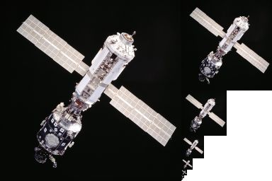
Usually, those mipmaps are pre-generated when creating the game assets using specific texture formats which allow the storage of mipmaps. The Khronos Group has defined the KTX file format which supports mipmaps and direct image compression in the GPU. However, we will not use that format here, we will see how to generate mipmaps by our own.
Let's go back to the VkTexture struct create function. The first we are going to do is calculate the number of mipmap levels that we need for a specific image:
File: src/eng/vk/vkTexture.zig
pub const VkTexture = struct {
    ...
    mipLevels: u32,
    ...
    pub fn create(vkCtx: *const vk.ctx.VkCtx, vkTextureInfo: *const VkTextureInfo) !VkTexture {
        const minDimension = @min(vkTextureInfo.width, vkTextureInfo.height);
        const mipLevels: u32 = @as(u32, @intFromFloat(std.math.floor(std.math.log2(@as(f64, @floatFromInt(minDimension)))))) + 1;

        const flags = vulkan.ImageUsageFlags{
            .transfer_dst_bit = true,
            .transfer_src_bit = true,
            .sampled_bit = true,
        };
        const vkImageData = vk.img.VkImageData{
            .width = vkTextureInfo.width,
            .height = vkTextureInfo.height,
            .usage = flags,
            .format = vkTextureInfo.format,
            .mipLevels = mipLevels,
        };
        const vkImage = try vk.img.VkImage.create(vkCtx, vkImageData);
        const imageViewData = vk.imv.VkImageViewData{ .format = vkTextureInfo.format, .levelCount = mipLevels };

        const vkImageView = try vk.imv.VkImageView.create(vkCtx.vkDevice, vkImage.image, imageViewData);
        ...
        return .{
            ...
            .mipLevels = mipLevels,
            ...
        };
    }
    ...
};
Since the number of images get scaled down by the power of two, we use the logarithm in base 2 to calculate the number of levels using the minimum value of the width, height of the image. We will be generating reduced versions of the original image iteratively, using the last scaled image as the source for the next one. This is the reason why you will see that we are using another usage flag for the VkImageData. We are setting the transfer_src_bit (VK_IMAGE_USAGE_TRANSFER_SRC_BIT) flag, since we will be using the image itself as a source to generate the different levels.
The next step is to modify the recordTransition function:
File: src/eng/vk/vkTexture.zig
pub const VkTexture = struct {
    ...
    pub fn recordTransition(self: *const VkTexture, vkCtx: *const vk.ctx.VkCtx, cmdHandle: vulkan.CommandBuffer) void {
        ...
        self.recordMipMap(vkCtx, cmdHandle);
        self.recorded = true;
    }
}
After the copy operation we call a new function called recordMipMap that will generate the different bitmaps. This function will use the cmdBlitImage Vulkan function to copy and transform the different mipmap levels of the image. Let's analyze that function:
File: src/eng/vk/vkTexture.zig
pub const VkTexture = struct {
    ...
    fn recordMipMap(self: *const VkTexture, vkCtx: *const vk.ctx.VkCtx, cmdHandle: vulkan.CommandBuffer) void {
        const device = vkCtx.vkDevice.deviceProxy;

        var barrier = [_]vulkan.ImageMemoryBarrier2{.{
            .old_layout = vulkan.ImageLayout.transfer_dst_optimal,
            .new_layout = vulkan.ImageLayout.transfer_src_optimal,
            .src_stage_mask = .{ .all_transfer_bit = true },
            .dst_stage_mask = .{ .all_transfer_bit = true },
            .src_access_mask = .{ .transfer_write_bit = true },
            .dst_access_mask = .{ .transfer_read_bit = true },
            .src_queue_family_index = vulkan.QUEUE_FAMILY_IGNORED,
            .dst_queue_family_index = vulkan.QUEUE_FAMILY_IGNORED,
            .subresource_range = .{
                .aspect_mask = .{ .color_bit = true },
                .base_array_layer = 0,
                .base_mip_level = 0,
                .level_count = 1,
                .layer_count = 1,
            },
            .image = self.vkImage.image,
        }};

        const depInfo = vulkan.DependencyInfo{
            .image_memory_barrier_count = barrier.len,
            .p_image_memory_barriers = &barrier,
        };

        var mipWidth: i32 = @as(i32, @intCast(self.width));
        var mipHeight: i32 = @as(i32, @intCast(self.height));
        ...
    }
    ...
};
We create a barrier to control the transition layouts, at this moment we just associate it to the image and the resource range. After this, we define the loop that will be generating the different levels:
File: src/eng/vk/vkTexture.zig
pub const VkTexture = struct {
    ...
    fn recordMipMap(self: *const VkTexture, vkCtx: *const vk.ctx.VkCtx, cmdHandle: vulkan.CommandBuffer) void {
        ...
        for (1..self.mipLevels) |i| {
            barrier[0].old_layout = vulkan.ImageLayout.transfer_dst_optimal;
            barrier[0].new_layout = vulkan.ImageLayout.transfer_src_optimal;
            barrier[0].src_access_mask = .{ .transfer_write_bit = true };
            barrier[0].dst_access_mask = .{ .transfer_read_bit = true };
            barrier[0].src_stage_mask = .{ .all_transfer_bit = true };
            barrier[0].dst_stage_mask = .{ .all_transfer_bit = true };
            barrier[0].subresource_range.base_mip_level = @as(u32, @intCast(i)) - 1;

            device.cmdPipelineBarrier2(cmdHandle, &depInfo);
            ...
        }
        ...
    }
    ...
}
We set the barrier parameters to wait for the image to transition from transfer_dst_optimal(VK_IMAGE_LAYOUT_TRANSFER_DST_OPTIMAL) to transfer_src_optimal (VK_IMAGE_LAYOUT_TRANSFER_SRC_OPTIMAL) in order to read from it. Remember that first we transitioned the image to the transfer_dst_optimal (VK_IMAGE_LAYOUT_TRANSFER_DST_OPTIMAL), we need now to read from that image to generate the different levels.
File: src/eng/vk/vkTexture.zig
pub const VkTexture = struct {
    ...
    fn recordMipMap(self: *const VkTexture, vkCtx: *const vk.ctx.VkCtx, cmdHandle: vulkan.CommandBuffer) void {
        ...
        for (1..self.mipLevels) |i| {
            ...
            const imageBlit = [_]vulkan.ImageBlit.{{
                .src_subresource = .{
                    .aspect_mask = .{ .color_bit = true },
                    .mip_level = @as(u32, @intCast(i)) - 1,
                    .base_array_layer = 0,
                    .layer_count = 1,
                },
                .src_offsets = [2]vulkan.Offset3D{
                    .{
                        .x = 0,
                        .y = 0,
                        .z = 0,
                    },
                    .{
                        .x = mipWidth,
                        .y = mipHeight,
                        .z = 1,
                    },
                },
                .dst_subresource = .{
                    .aspect_mask = .{ .color_bit = true },
                    .mip_level = @as(u32, @intCast(i)),
                    .base_array_layer = 0,
                    .layer_count = 1,
                },
                .dst_offsets = [2]vulkan.Offset3D{
                    .{
                        .x = 0,
                        .y = 0,
                        .z = 0,
                    },
                    .{
                        .x = if (mipWidth > 1) @divTrunc(mipWidth, 2) else 1,
                        .y = if (mipHeight > 1) @divTrunc(mipHeight, 2) else 1,
                        .z = 1,
                    },
                },
            }};

            device.cmdBlitImage(
                cmdHandle,
                self.vkImage.image,
                vulkan.ImageLayout.transfer_src_optimal,
                self.vkImage.image,
                vulkan.ImageLayout.transfer_dst_optimal,
                &imageBlit,
                vulkan.Filter.linear,
            );
            ...
        }
        ...
    }
    ...
};
As we mentioned before, we are using the cmdBlitImage function to create the mip levels. This function copies regions of a source image into a destination image and is able to perform format conversions. The parameters are:
- The command buffer where will be recording this operation.
- The source image.
- The layout where that source image should be.
- The destination image.
- The layout where that destination image should be. We are using the same image as a source and as a destination. - The regions to blit.
- The filter to apply if the blit operation requires scaling. In our case, we select the
linear(VK_FILTER_LINEAR) filter.
Prior to invoking the cmdBlitImage function we need to define the regions by defining a ImageBlit array. This structure defines the following parameters:
src_offsets: This parameter defines the boundaries to be used in the blit operation for the source image. In our case, in the first iteration is the width and height of the image. In the next executions of the loop it will be progressively divided by two. It shall contain two elements.src_subresource: It defines the sub-resource to blit from. In the first iteration it will be the base level, the level0. Then it will be progressively augmented, using the level constructed in the previous iteration as the source for the current one. in itssrc_subresourcethe sub-resource to blit from into the sub-resource defined by thedstSubresource.dst_offsets: This parameter defines the boundaries to be used in the blit operation for the destination image. As you can see is the same size as the source image divided by two.dst_offsets: It defines the sub-resource to blit to.
To complete the loop, we transition the image to the shader_read_only_optimal (VK_IMAGE_LAYOUT_SHADER_READ_ONLY_OPTIMAL) layout in order to be able to access it from a shader:
File: src/eng/vk/vkTexture.zig
pub const VkTexture = struct {
    ...
    fn recordMipMap(self: *const VkTexture, vkCtx: *const vk.ctx.VkCtx, cmdHandle: vulkan.CommandBuffer) void {
        ...
        for (1..self.mipLevels) |i| {
            ...
            barrier[0].old_layout = vulkan.ImageLayout.transfer_src_optimal;
            barrier[0].new_layout = vulkan.ImageLayout.shader_read_only_optimal;
            barrier[0].src_access_mask = .{ .transfer_read_bit = true };
            barrier[0].dst_access_mask = .{ .shader_read_bit = true };
            barrier[0].src_stage_mask = .{ .all_transfer_bit = true };
            barrier[0].dst_stage_mask = .{ .fragment_shader_bit = true };

            device.cmdPipelineBarrier2(cmdHandle, &depInfo);

            if (mipWidth > 1) {
                mipWidth = @divTrunc(mipWidth, 2);
            }
            if (mipHeight > 1) {
                mipHeight = @divTrunc(mipHeight, 2);
            }
        }
        ...
    }
    ...
};
When we finalize the loop we need to transition the layout of the last mip level:
File: src/eng/vk/vkTexture.zig
pub const VkTexture = struct {
    ...
    fn recordMipMap(self: *const VkTexture, vkCtx: *const vk.ctx.VkCtx, cmdHandle: vulkan.CommandBuffer) void {
        ...
        const lastMip: u32 = self.mipLevels - 1;
        // Record transition to read only optimal
        const endBarriers = [_]vulkan.ImageMemoryBarrier2.{{
            .old_layout = vulkan.ImageLayout.transfer_dst_optimal,
            .new_layout = vulkan.ImageLayout.shader_read_only_optimal,
            .src_stage_mask = .{ .all_transfer_bit = true },
            .dst_stage_mask = .{ .fragment_shader_bit = true },
            .src_access_mask = .{ .transfer_write_bit = true },
            .dst_access_mask = .{ .shader_read_bit = true },
            .src_queue_family_index = vulkan.QUEUE_FAMILY_IGNORED,
            .dst_queue_family_index = vulkan.QUEUE_FAMILY_IGNORED,
            .subresource_range = .{
                .aspect_mask = .{ .color_bit = true },
                .base_mip_level = lastMip,
                .level_count = 1,
                .base_array_layer = 0,
                .layer_count = 1,
            },
            .image = self.vkImage.image,
        }};
        const endDepInfo = vulkan.DependencyInfo{
            .image_memory_barrier_count = endBarriers.len,
            .p_image_memory_barriers = &endBarriers,
        };
        device.cmdPipelineBarrier2(cmdHandle, &endDepInfo);
    }
};
One question that you may have now, is that, if now each texture can have different mip map levels, should we have specific texture samplers per image. If you remember, when creating the samplers, we used the SamplerCreateInfo struct which had the following attribute: max_lod. This should have the number of mip map levels. Should we have separate texture samplers per texture? Not really, we set the max_lod attribute to LOD_CLAMP_NONE (VK_LOD_CLAMP_NONE). This flag basically says that we can use all the available levels. Therefore, no need to create separate samplers.
Camera
We will create a new struct named ViewData to support moving around the scene. It will be included in the src/eng/scene.zig file and its is quite simple:
File: src/eng/scene.zig
pub const ViewData = struct {
    pos: zm.Vec,
    yaw: f32,
    pitch: f32,
    viewMatrix: zm.Mat,

    pub fn addRotation(self: *ViewData, pitch: f32, yaw: f32) void {
        self.pitch += pitch;
        self.yaw += yaw;
        self.recalculate();
    }

    pub fn create() ViewData {
        var viewData = ViewData{
            .pos = zm.Vec{ 0.0, 0.0, 0.0, 0.0 },
            .yaw = -std.math.pi / 2.0,
            .pitch = 0,
            .viewMatrix = zm.identity(),
        };
        viewData.recalculate();
        return viewData;
    }

    pub fn moveBack(self: *ViewData, inc: f32) void {
        const delta = self.forwardDir() * zm.splat(zm.Vec, inc);
        self.pos = self.pos - delta;
        self.recalculate();
    }

    pub fn moveForward(self: *ViewData, inc: f32) void {
        const delta = self.forwardDir() * zm.splat(zm.Vec, inc);
        self.pos = self.pos + delta;
        self.recalculate();
    }

    pub fn moveLeft(self: *ViewData, inc: f32) void {
        const delta = self.rightDir() * zm.splat(zm.Vec, inc);
        self.pos = self.pos - delta;
        self.recalculate();
    }

    pub fn moveRight(self: *ViewData, inc: f32) void {
        const delta = self.rightDir() * zm.splat(zm.Vec, inc);
        self.pos = self.pos + delta;
        self.recalculate();
    }

    pub fn moveUp(self: *ViewData, inc: f32) void {
        const delta = upDir() * zm.splat(zm.Vec, inc);
        self.pos = self.pos + delta;
        self.recalculate();
    }

    pub fn moveDown(self: *ViewData, inc: f32) void {
        const delta = upDir() * zm.splat(zm.Vec, inc);
        self.pos = self.pos - delta;
        self.recalculate();
    }

    fn forwardDir(self: *const ViewData) zm.Vec {
        return zm.normalize3(zm.f32x4(
            @cos(self.pitch) * @cos(self.yaw),
            @sin(self.pitch),
            @cos(self.pitch) * @sin(self.yaw),
            0.0,
        ));
    }

    fn rightDir(self: *const ViewData) zm.Vec {
        const up = zm.f32x4(0.0, 1.0, 0.0, 0.0);
        return zm.normalize3(zm.cross3(self.forwardDir(), up));
    }

    pub fn recalculate(self: *ViewData) void {
        // Avoid gimbal lock
        self.pitch = std.math.clamp(
            self.pitch,
            -std.math.pi / 2.0 + 0.001,
            std.math.pi / 2.0 - 0.001,
        );

        const forward = self.forwardDir();
        const target = self.pos + forward;
        const up = upDir();

        self.viewMatrix = zm.lookAtRh(
            self.pos,
            target,
            up,
        );
    }

    fn upDir() zm.Vec {
        return zm.f32x4(0.0, 1.0, 0.0, 0.0);
    }
};
This struct, in essence, stores the view matrix, which can be modified by the different functions that it provides to change its position, to apply rotation or to move around the scene. It uses the zmath library to calculate up and forward vectors to move.
This struct will now be part of the Camera struct:
File: src/eng/scene.zig
pub const Camera = struct {
    ...
    viewData: ViewData,

    pub fn create() Camera {
        ...
        const viewData = ViewData.create();
        return .{ .projData = projData, .viewData = viewData };
    }
};
We will see later on how to use it while recording the render commands.
Completing the changes
Now it is time to modify the ScnRender struct. We will need a buffer per frame in flight to store camera matrices. Unlike the projection matrix, the contents of the view matrix will change from frame to frame so to avoid modifying the data while we render, we need this array. Therefore, the buffCamera buffer will be now an array of buffers and will be renamed to buffsCamera:
File: src/eng/renderScn.zig
pub const RenderScn = struct {
    buffsCamera: []vk.buf.VkBuffer,
    ...
    pub fn cleanup(self: *RenderScn, allocator: std.mem.Allocator, vkCtx: *const vk.ctx.VkCtx) void {
        ...
        for (self.buffsCamera) |*buffer| {
            buffer.cleanup(vkCtx);
        }
        allocator.free(self.buffsCamera);
    }

    pub fn create(allocator: std.mem.Allocator, io: std.Io, vkCtx: *vk.ctx.VkCtx) !RenderScn {
        ...
        const buffsCamera = try createCamBuffers(allocator, vkCtx, descLayoutVtx);
        ...
        // Pipeline
        const vkPipelineCreateInfo = vk.pipe.VkPipelineCreateInfo{
            ...
            .useBlend = true,
            ...
        };
        const vkPipeline = try vk.pipe.VkPipeline.create(allocator, vkCtx, &vkPipelineCreateInfo);

        return .{
            .buffsCamera = buffsCamera,
            ...
        };
    }
    ...
};
In addition to that, when creating the pipeline we need to setup the useBlend attribute to true to enable transparencies. The createCamBuffers function is defined as follows:
File: src/eng/renderScn.zig
pub const RenderScn = struct {
    ...
    fn createCamBuffers(allocator: std.mem.Allocator, vkCtx: *vk.ctx.VkCtx, descLayout: vk.desc.VkDescSetLayout) ![]vk.buf.VkBuffer {
        const buffers = try allocator.alloc(vk.buf.VkBuffer, com.common.FRAMES_IN_FLIGHT);
        for (buffers, 0..) |*buffer, i| {
            const id = try std.fmt.allocPrint(allocator, "{s}{d}", .{ DESC_ID_CAM, i });
            defer allocator.free(id);
            buffer.* = try vk.util.createHostVisibleBuff(
                allocator,
                vkCtx,
                id,
                @sizeOf(zm.Mat) * 2,
                .{ .uniform_buffer_bit = true },
                descLayout,
            );
        }
        return buffers;
    }
    ...
};
The code is quite similar to the previous version, the difference is that we now create one buffer per frame in flight and associate them with its own descriptor set, which will be identified by the DESC_ID_CAM constant plus the position in the array of buffers. When rendering we will select which descriptor set to bind depending on the frame in flight we are in.
We need also to modify the render struct to use the view matrices and to render transparent objects in the last place.
File: src/eng/renderScn.zig
pub const RenderScn = struct {
    ...
    pub fn render(
        self: *RenderScn,
        vkCtx: *const vk.ctx.VkCtx,
        engCtx: *const eng.engine.EngCtx,
        vkCmd: vk.cmd.VkCmdBuff,
        modelsCache: *const eng.mcach.ModelsCache,
        materialsCache: *const eng.mcach.MaterialsCache,
        imageIndex: u32,
        frameIdx: u8,
    ) !void {
        ...
        try self.updateCamera(vkCtx, frameIdx, &scene.camera.projData.projMatrix, &scene.camera.viewData.viewMatrix);
        ...
        // Bind descriptor sets
        const vkDescAllocator = vkCtx.vkDescAllocator;
        var descSets = try std.ArrayList(vulkan.DescriptorSet).initCapacity(allocator, 3);
        defer descSets.deinit(allocator);
        const camDescIdc = try std.fmt.allocPrint(allocator, "{s}{d}", .{ DESC_ID_CAM, frameIdx });
        defer allocator.free(camDescIdc);
        ...
        self.renderEntities(vkCtx, engCtx, modelsCache, materialsCache, cmdHandle, false);
        self.renderEntities(vkCtx, engCtx, modelsCache, materialsCache, cmdHandle, true);

        device.cmdEndRendering(cmdHandle);
    }
    ...
};
The render function now receives frameIdx which will be the frame in flight. The updateCamera function needs to be modified to take into consideration the mew view matrix and the frame in flight index. When binding the descriptor set we will select the one associated to current frame in flight for the camera descriptor set. The recording of drawing commands for the entities has now been extracted to the renderEntities whose last parameters is a flag to control which entities we draw, the ones that have transparent materials or the ones that not.
The renderEntities code is similar to the one used in previous chapter, we just filter entities that match the transparency property specified as a function argument.
File: src/eng/renderScn.zig
pub const RenderScn = struct {
    ...
    fn renderEntities(
        self: *RenderScn,
        vkCtx: *const vk.ctx.VkCtx,
        engCtx: *const eng.engine.EngCtx,
        modelsCache: *const eng.mcach.ModelsCache,
        materialsCache: *const eng.mcach.MaterialsCache,
        cmdHandle: vulkan.CommandBuffer,
        transparent: bool,
    ) void {
        const device = vkCtx.vkDevice.deviceProxy;
        const offset = [_]vulkan.DeviceSize{0};
        var iter = engCtx.scene.entitiesMap.valueIterator();

        while (iter.next()) |entityRef| {
            const entity = entityRef.*;
            const vulkanModel = modelsCache.modelsMap.get(entity.modelId);
            if (vulkanModel) |*vm| {
                for (vm.meshes.items) |mesh| {
                    var materialIdx: u32 = 0;
                    if (materialsCache.materialsMap.getIndex(mesh.materialId)) |idx| {
                        materialIdx = @as(u32, @intCast(idx));
                        const material = materialsCache.materialsMap.get(mesh.materialId).?;
                        if (material.transparent != transparent) {
                            continue;
                        }
                    }
                    self.setPushConstants(vkCtx, cmdHandle, entity, materialIdx);
                    device.cmdBindIndexBuffer(cmdHandle, mesh.buffIdx.buffer, 0, vulkan.IndexType.uint32);
                    device.cmdBindVertexBuffers(cmdHandle, 0, @ptrCast(&mesh.buffVtx.buffer), &offset);
                    device.cmdDrawIndexed(cmdHandle, @as(u32, @intCast(mesh.numIndices)), 1, 0, 0, 0);
                }
            } else {
                std.log.warn("Could not find model {s}", .{entity.modelId});
            }
        }
    }
    ...
};
The updateCamera function needs to be updated as follows:
File: src/eng/renderScn.zig
pub const RenderScn = struct {
    ...
    fn updateCamera(
        self: *RenderScn,
        vkCtx: *const vk.ctx.VkCtx,
        frameIdx: u8,
        projMatrix: *const zm.Mat,
        viewMatrix: *const zm.Mat,
    ) !void {
        const buffData = try self.buffsCamera[frameIdx].map(vkCtx);
        defer self.buffsCamera[frameIdx].unMap(vkCtx);
        const gpuBytes: [*]u8 = @ptrCast(buffData);

        const projMatrixBytes = std.mem.asBytes(projMatrix);
        const projMatrixPtr: [*]align(16) const u8 = projMatrixBytes.ptr;

        const viewMatrixBytes = std.mem.asBytes(viewMatrix);
        const viewMatrixPtr: [*]align(16) const u8 = viewMatrixBytes.ptr;

        @memcpy(gpuBytes[0..@sizeOf(zm.Mat)], projMatrixPtr[0..@sizeOf(zm.Mat)]);
        @memcpy(gpuBytes[@sizeOf(zm.Mat) .. @sizeOf(zm.Mat) * 2], viewMatrixPtr[0..@sizeOf(zm.Mat)]);
    }
    ...
};
The vertex shader (scn_vtx.glsl) needs to be updated now that the uniform not only contains the projection matrix but also the view matrix:
File: res/shaders/scn_vtx.glsl
#version 450

layout(location = 0) in vec3 inPos;
layout(location = 1) in vec2 inTextCoords;

layout(location = 0) out vec2 outTextCoords;

layout(set = 0, binding = 0) uniform CamUniform {
    mat4 projMatrix;
    mat4 viewMatrix;
} camUniform;

layout(push_constant) uniform pc {
    mat4 modelMatrix;
} push_constants;

void main()
{
    gl_Position   = camUniform.projMatrix * camUniform.viewMatrix * push_constants.modelMatrix * vec4(inPos, 1);
    outTextCoords = inTextCoords;
}
The render function of the RenderScn struct now needs to access to the currentFrame so we need to update the Render struct:
File: src/eng/render.zig
pub const Render = struct {
    ...
    pub fn render(self: *Render, engCtx: *eng.engine.EngCtx) !void {
        ...
        try self.renderScn.render(
            &self.vkCtx,
            engCtx,
            vkCmdBuff,
            &self.modelsCache,
            &self.materialsCache,
            imageIndex,
            self.currentFrame,
        );
        ...
    }
    ...
};
The last step is to change the Game struct to use the camera and a new model. In this case we will be using the famous Sponza model (we are using the models from GitHub - KhronosGroup/glTF-Sample-Models: glTF Sample Models).
File: src/main.zig
const Game = struct {
    const ENTITY_ID: []const u8 = "SponzaEntity";
    ...
    pub fn init(self: *Game, engCtx: *eng.engine.EngCtx, arenaAlloc: std.mem.Allocator) !eng.engine.InitData {
        _ = self;

        const sponzaModel = try eng.mdata.loadModel(arenaAlloc, engCtx.io,  "res/models/sponza/Sponza.json");
        const models = try arenaAlloc.alloc(eng.mdata.ModelData, 1);
        models[0] = sponzaModel;

        const sponzaEntity = try eng.ent.Entity.create(engCtx.allocator, ENTITY_ID, sponzaModel.id);
        sponzaEntity.setPos(0.0, 0.0, -4.0);
        sponzaEntity.scale = 0.01;
        sponzaEntity.update();
        try engCtx.scene.addEntity(sponzaEntity);

        var materials = try std.ArrayList(eng.mdata.MaterialData).initCapacity(arenaAlloc, 1);
        const sponzaMaterials = try eng.mdata.loadMaterials(arenaAlloc, engCtx.io, "res/models/sponza/Sponza-mat.json");
        try materials.appendSlice(arenaAlloc, sponzaMaterials.items);

        var viewData = &engCtx.scene.camera.viewData;
        viewData.pos = zm.Vec{ 0.0, 3.0, -4.0, 0.0 };
        viewData.addRotation(std.math.degreesToRadians(0), std.math.degreesToRadians(90));
        return .{ .models = models, .materials = materials };
    }
    ...
};
We have modified the input function to update the camera position with the mouse movement when pressing the right button:
File: src/main.zig
const Game = struct {
    ...
    pub fn input(self: *Game, engCtx: *eng.engine.EngCtx, deltaSec: f32) void {
        _ = self;
        const inc: f32 = 10;
        var viewData = &engCtx.scene.camera.viewData;
        if (engCtx.wnd.isKeyPressed(sdl3.Scancode.w)) {
            viewData.moveForward(inc * deltaSec);
        } else if (engCtx.wnd.isKeyPressed(sdl3.Scancode.s)) {
            viewData.moveBack(inc * deltaSec);
        }
        if (engCtx.wnd.isKeyPressed(sdl3.Scancode.a)) {
            viewData.moveLeft(inc * deltaSec);
        } else if (engCtx.wnd.isKeyPressed(sdl3.Scancode.d)) {
            viewData.moveRight(inc * deltaSec);
        }
        if (engCtx.wnd.isKeyPressed(sdl3.Scancode.up)) {
            viewData.moveUp(inc * deltaSec);
        } else if (engCtx.wnd.isKeyPressed(sdl3.Scancode.down)) {
            viewData.moveDown(inc * deltaSec);
        }

        const mouseState = engCtx.wnd.mouseState;
        if (mouseState.flags.right) {
            const mouseInc: f32 = 0.1;
            viewData.addRotation(std.math.degreesToRadians(-mouseState.deltaY * mouseInc), std.math.degreesToRadians(-mouseState.deltaX * mouseInc));
        }
    }
    ...
};
The update function is empty now:
File: src/main.zig
const Game = struct {
    ...
    pub fn update(self: *Game, engCtx: *eng.engine.EngCtx, deltaSec: f32) void {
        _ = self;
        _ = engCtx;
        _ = deltaSec;
    }
    ...
};
With all of these changes you will be able to see the Sponza model. You will be able to move around the scene, and you can see that transparent objects are properly rendered.